Effective projected area (EPA)
Summary
The effective projected area (EPA) of a camera (including its mount) is used to calculate wind loads on the camera in various outdoor installations where wind speed and air density may vary.
You can find the EPA values of Axis cameras and mounts in datasheets or request them from Axis support. The given values are worst-case approximations.
Introduction
The EPA value of a camera (including its mount) is needed in order to calculate the wind-induced load on the camera in an outdoor installation, such as a pole mount or a parapet mount. You can find the EPA values of Axis cameras and mounts in datasheets or request them from Axis support.
This white paper presents briefly how EPA values are calculated at Axis and how they can be used to determine approximate wind loads.
Background – wind load on outdoor camera installations
Knowing what wind loads to expect is important when you install a camera outdoors. This way you can make sure that the installation is sturdy enough and has the adequate pole dimension, bolt connections of the correct size, and so on. Using the right type of installation can also minimize the effects of the wind load on the camera. This is especially important for cameras that use optical zoom to monitor objects far away, because these types of cameras are generally more sensitive to vibrations when zoomed in.
The wind-induced force on a camera is affected by several factors. Two of them (wind speed and air density) depend on the installation environment, while the other two (camera size and the camera’s drag coefficient) depend on the camera’s physical aspects. These physical aspects, when combined, define the EPA.
For an exact calculation of wind loads you also need to consider a few other, more complex, wind factors, such as natural frequency and vortex shedding. While outside the scope of this paper, these factors may be important in critical installations.
The wind load (drag force) equation
The drag force (FD), on an object is based on the frontal area (A) of the object (i.e., its cross section), the drag coefficient (Cd), of the object, the air density (ρ), and the wind speed (v). The drag force is measured in N and calculated as follows:
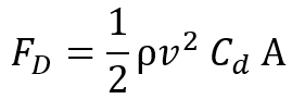
Air density (ρ): Air density, like air pressure, decreases with increasing altitude. The air density also changes with variations in atmospheric pressure, temperature, and humidity. For calculations of the drag force, the air density is usually set to 1.2 kg/m3, which is the air pressure at sea level and a temperature of 15 °C.
Wind speed (v): The wind speed is factored in twice (i.e., v2) in the calculation, which means that it has a very large impact on the drag force. The unit of the wind speed is m/s.
Frontal area (A): Choosing the frontal area to be the object’s largest cross section means assuming the worst-case scenario regarding wind direction. The unit of the frontal area is m2.
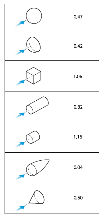
Drag coefficient (Cd): The drag coefficient is a dimensionless value that can be used to quantify the drag or resistance of an object (such as a camera or a mount) in a fluid environment, such as air. The drag coefficient varies according to shape and direction of the wind and can only be precisely measured with the use of wind tunnels. The lower the drag coefficient (for a given object size), the less wind resistance. A regular sphere usually has a Cd of 0.47 whereas a cube, with the same cross section area, usually has a Cd of 1.05.
EPA – a measure that is independent of the surroundings
The two environment-independent factors of the drag force equation form the EPA:
Effective projected area = Cd A
The total EPA of a camera and its mount is given by adding the camera’s EPA to the mount’s EPA. Knowing the EPA of a specific camera/mount combination enables calculation of wind-induced loads in various installation locations with different wind speeds and air densities.
How EPA values are determined at Axis
The EPA values for Axis cameras and mounts are always calculated with a drag coefficient of 1. This is to assume a worst-case approximation. In reality, the drag coefficient of an Axis camera is relatively small but depending on how the camera is installed, wind loads can still affect the surveillance results through vibrations or insufficient mounting options.
By choosing the frontal area value to be the largest cross section of the camera or mount, we assume the worst-case scenario also when it comes to wind direction. Because the drag coefficient Cd is set to 1, the EPA of a camera or mount is the same as the largest cross section, measured in m2.
Example: Determining the wind load on a camera installation
The illustration shows AXIS Q6315-LE PTZ Network Camera mounted on AXIS T91G61 Wall Mount. The total EPA of the installation is the sum of the camera’s EPA and the mount’s EPA.
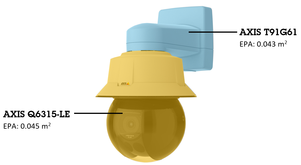
Using the air density value of 1.2 kg/m3, the drag force equation yields a wind load on the installation of:
- approximately 1.3 N at a wind speed of 5 m/s.
- approximately 33 N at a wind speed of 25 m/s.