Pixel density and DORI
Summary
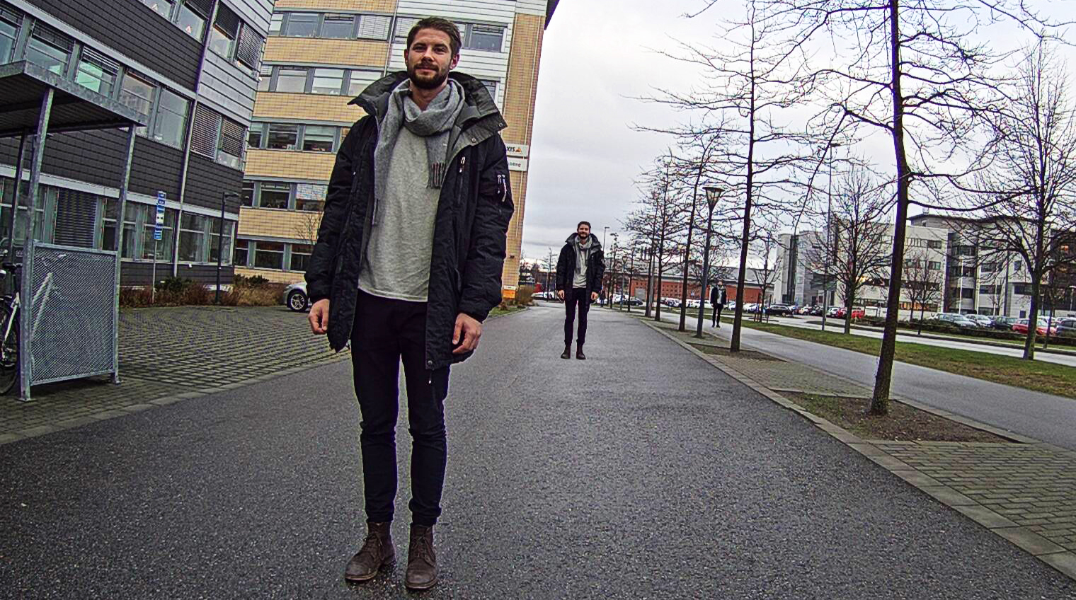
Common operational requirements in video surveillance are detection, observation, recognition, and identification (summarized as “DORI”) of individuals or objects in the footage.
Once you have decided what level of detail you need, the pixel density model provides basic guidelines to help you find out which camera resolution you need. The model is based on how many pixels are needed across a human face for identification, but the pixel density is often expressed in pixels per meter or per foot.
| Operational requirement | Pixel density needed | ||
|---|---|---|---|
| Detection | 4 px/face | 25 px/m | 8 px/ft |
| Observation | 10 px/face | 63 px/m | 20 px/ft (19 px/ft)* |
| Recognition | 20 px/face | 125 px/m | 40 px/ft (38 px/ft)* |
| Identification | 40 px/face | 250 px/m | 80 px/ft (76 px/ft)* |
* The more precise convertions from px/m are used in product datasheets but the rounded values tend to be used in practice.
The pixel density model offers guidelines that are easy to use. In reality, however, there are always additional factors, such as light direction, optics quality, and image compression, that may affect the result. Axis provides online tools that employ the pixel density model to help you plan a surveillance system with the right level of detail in the right places, taking both pixel density and many other factors into account:
AXIS Site Designer incorporates a camera selector tool that helps you choose a suitable camera based on several criteria, including lighting conditions and which level of detail you need at defined distances.
Lens calculator determines camera coverage and pixel density at defined distances for different camera/lens combinations.
Pixel counter is an integrated tool in Axis cameras, for easy validation of the operational requirements. It is a simple visual aid that displays a frame with its width and height measured in pixels, in the camera live view.
AXIS Plugin for Autodesk® Revit® allows you to select and place interactive Axis products directly in your Autodesk Revit building plan and incorporate surveillance into your design. The plugin includes an embedded product selector and lets you verify coverage and adjust settings to match the scene.
Calculations of distances related to the DORI definitions are also provided in the product datasheets of new Axis products.
It should be noted that the specified operational requirements are valid in situations where visual video images are interpreted by human operators. For video analytics applications or other systems where image analysis is done by software, other definitions apply. Thermal imaging (using thermal cameras) also defines the operational requirements differently.
It should also be noted that if an external display is used to monitor the scene, the ability to detect, observe, recognize, or identify individuals depends highly on the screen resolution of that display.
Introduction
When designing a surveillance system it is important to keep in mind what the purpose of the system is. You may use datasheets and technical specifications to find out which camera has the best resolution, but in order to optimize cost and effort you should focus on what camera and setup will fit your operational requirements. For example, do you need to be able to identify individuals from the footage, or do you just need to detect whether anyone is present at all?
This white paper provides guidance on how to select a camera that meets the operational requirements of your system. We discuss pixel density requirements and Axis tools for planning a surveillance setup.
Operational requirements
We distinguish between the need for detection, observation, recognition, and identification. These requirements are sometimes referred to by the acronym DORI.
| Operational requirement | Level of detail |
|---|---|
| Detection | It is possible to determine whether or not any individual is present. |
| Observation | It is possible to determine how many people are present and to see characteristic details of individuals, such as distinctive clothing. |
| Recognition | It is possible for a viewer to determine whether or not an individual shown is the same as someone they have seen before. |
| Identification | It is possible to identify an individual. |
The specifications for these requirements (for visual cameras), come from the international standard IEC 62676-4 (Video Surveillance Systems for Use in Security Applications – Part 4: Application guidelines).
It should be noted that the specifications for these operational requirements are valid in situations where visual video images are interpreted by human operators. For video analytics applications or other systems where image analysis is done by software, other definitions for the operational requirements would apply. Thermal imaging (using thermal cameras) also uses a different set of specifications for operational requirements.
The pixel density model - relating operational requirements to camera resolution
Once you have decided the levels of detail you need from your surveillance system, you need to find cameras that will meet the requirements. This is where the pixel density model comes in, associating the level of detail with camera resolution.
What is the pixel density model?
The basis of the model is the number of pixels needed to represent the width of a human face, with its distinctive identifying features, to the requested level of detail. In order to get a standardized pixel density requirement, the pixel density of the face can be recalculated to the corresponding number of pixels needed per meter or per foot, based on the assumption that an average human face has a width of 16 cm, or 6 5/16 inches. The table lists the resulting pixel densities for the different operational requirement categories.
| Operational requirement | Pixel density needed | ||
|---|---|---|---|
| Detection | 4 px/face | 25 px/m | 8 px/ft |
| Observation | 10 px/face | 63 px/m | 20 px/ft (19 px/ft)* |
| Recognition | 20 px/face | 125 px/m | 40 px/ft (38 px/ft)* |
| Identification | 40 px/face | 250 px/m | 80 px/ft (76 px/ft)* |
* IEC 62676-4 lists the values in px/m. For markets that measure in feet instead of meters, we convert the standardized values to px/ft. Axis product datasheets list accurately converted values (19, 38, and 76 px/ft), and use them for distance calculations. In practice, however, the more rounded values (20, 40, and 80 px/ft) are often used.
It is usually recommended, for example in IEC 62676-4, to have at least 40 pixels across the width of a human face to enable identification. If possible, an even higher pixel density can be beneficial and provide a safety margin for worst-case conditions, such as sub-optimal lighting and individuals not directly facing the camera.
The pixel density you can achieve in a specific camera setup depends on, among other things, the distance between the camera and the individual or object of interest. An individual that is further away will have a lower pixel density than an individual closer to the camera.
A simplified model of a complex reality
We must remember that the pixel density model is a simplified model of a complex reality. The model can be used to give guidance, but there is no guarantee that complying with this simplified rule of thumb will enable a camera to fulfill the operational requirements. Also, if an installation does not comply with the pixel density guidelines, this does not necessarily mean that the operational requirements will not be met. In reality there are always other factors such as light direction, optics quality, and image compression that affect the result. Axis offers several online tools for designing a surveillance site, taking both pixel density and many other factors into account.
The choice of optics is particularly important, and a science on its own, which is why it is advisable to work with vendors who supply cameras that have been tested end-to-end with the included lens.
It should also be noted that if an external display is used to monitor the scene, the ability to detect, observe, recognize, or identify individuals depends highly on the screen resolution of that display.
Tools for site design
Axis offers several tools that relate pixel density and operational requirements to the features of your scene and your camera. These tools can help you in designing a complete surveillance site, with fulfilled operational requirements.
Calculations of distances related to the DORI definitions are also provided in the product datasheets of new Axis products for which DORI is relevant. These calculations use the center of the image as the reference point and consider lens distortion.
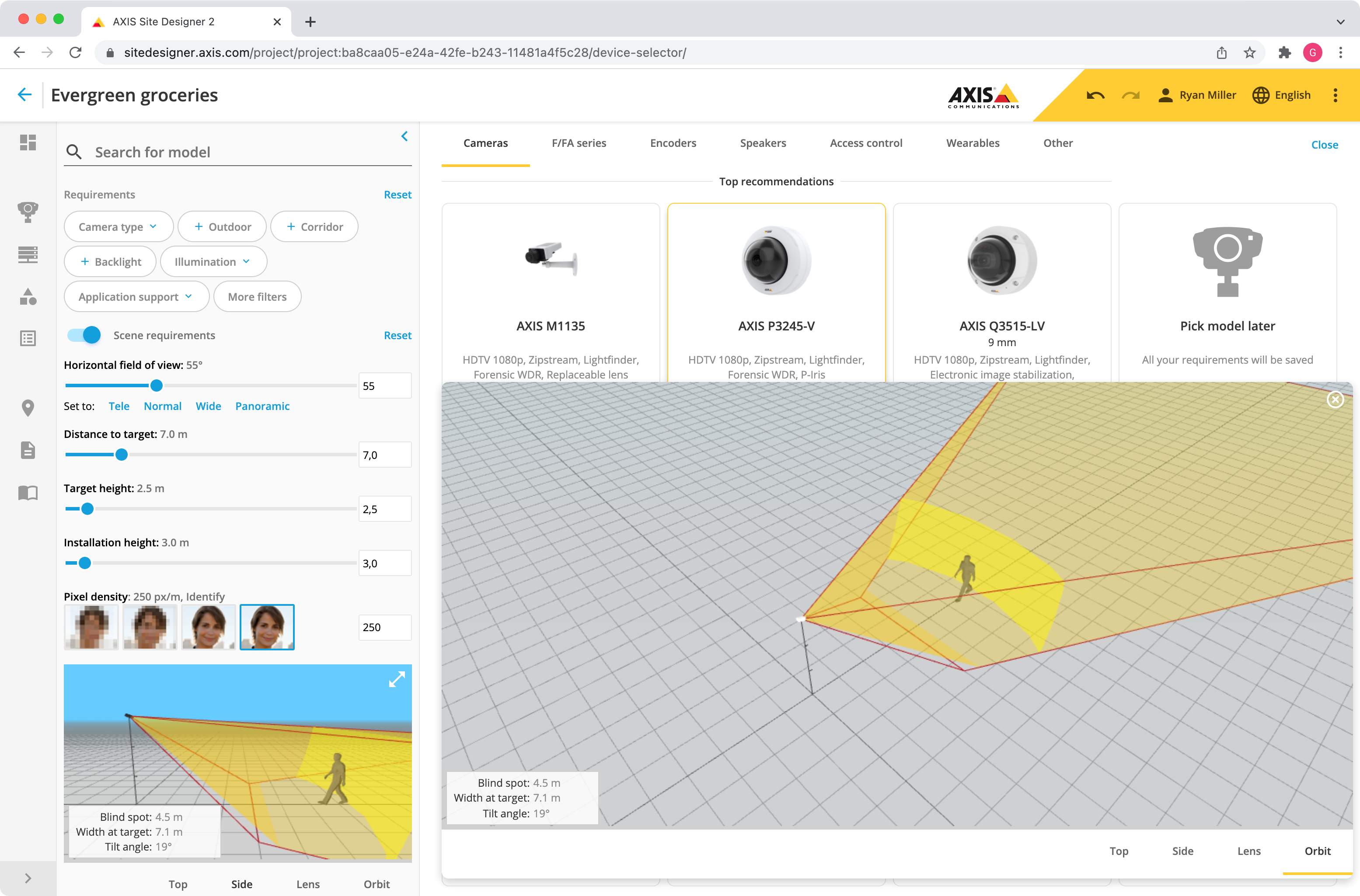
AXIS Site Designer
AXIS Site Designer is a comprehensive online site-planning tool helping you to pick the cameras, accessories, and recording solutions you need. The camera selector tool helps you choose a suitable camera based on different criteria including which pixel density and level of detail you need at defined distances, for different lighting conditions.
In AXIS Site Designer, it is possible to visualize the achievable pixel densities of each camera within the camera's entire coverage, with each operational requirement displaying as a different shade of color.
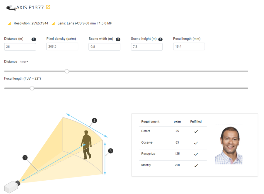
Lens calculator
The online lens calculator tool determines camera coverage and pixel density at defined distances for different camera/lens combinations.
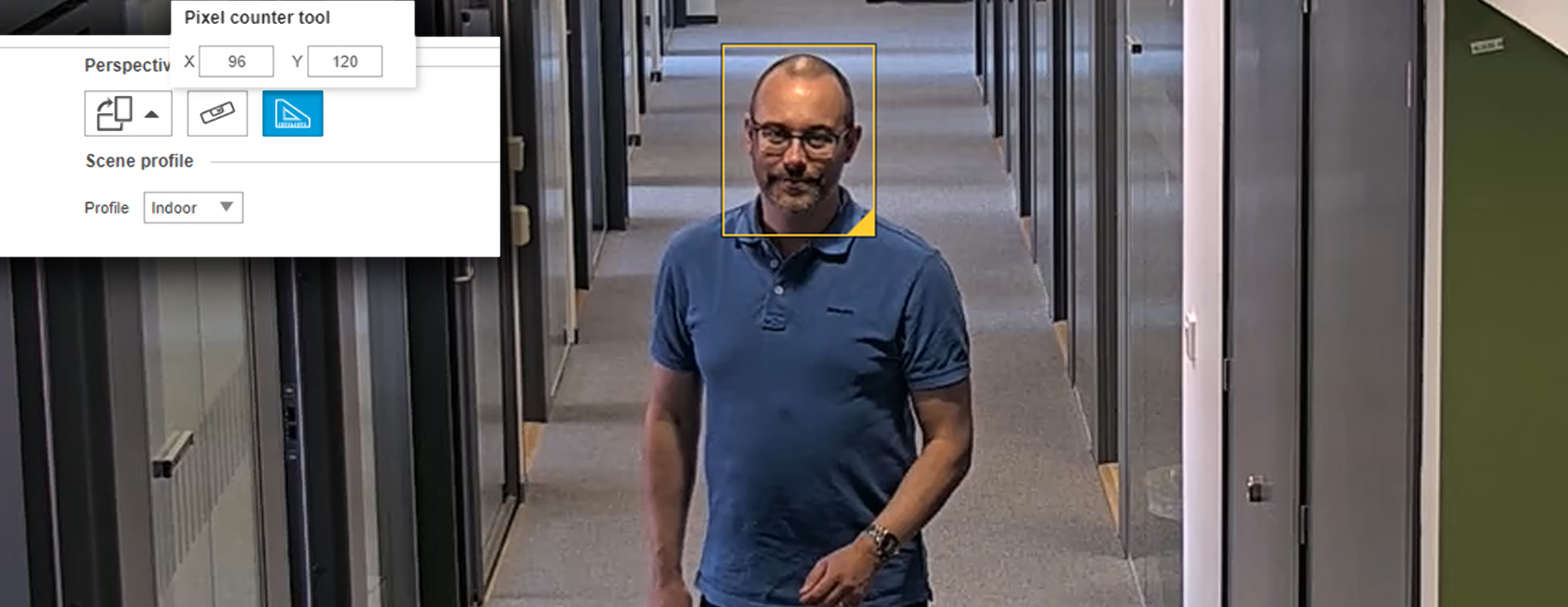
Pixel counter
Pixel counter is an integrated tool in Axis cameras, enabling you to easily validate the operational requirements when setting up the camera. The pixel counter is a simple visual aid, shaped as a frame. It can be displayed in the camera live view with a corresponding counter to show the width and height, in pixels, of the frame. It can be adjusted and moved around in the image through drag-and-drop.
AXIS Plugin for Autodesk® Revit®
AXIS Plugin for Autodesk Revit allows you to place 3D camera models of selected Axis cameras into your Autodesk Revit building plan. The models provide camera coverage (including DORI areas) allowing you to verify the coverage with configurable properties to match the surveillance requirement in your building project. The model’s coverage corresponds to the camera’s real-life coverage and provides users with a reliable planning option in 3D.